Multifunction meter
- Direct voltage (DCV): 0.1 mV to 1000 V
- Alternating voltage (ACV): 0.1 V – 750 V
- Direct current (DCA): 0.1 mA - 10 A
- Resistance: 0.1 – 2 M
- Diode voltage drop and hFE value for PNP and NPN transistors
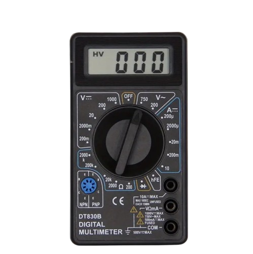
Digital multimeter DT-830B (black) with test leads
The DT830B Digital Multimeter is a compact and lightweight tool - a great option if you need a cheap and reliable meter. The heart of the device is the ICL7106 chip, combined with a large 3 1/2 digit, 7-segment, 0.5 inch high liquid crystal display (LCD) with a maximum reading of 1999.
Instructions
Alternating voltage measurement (ACV)
- Connect the red test lead to the "V?mA" terminal and the black to the "COM" terminal.
- Turn the selector switch to the desired V~ position.
- Connect the test leads to the object to be measured and read the voltage on the LCD display.
Direct current voltage measurement (DCV)
- Connect the red test lead to the "V?mA" terminal and the black to the "COM" terminal.
- Select the appropriate measurement range. If the voltage to be measured is unknown, start with the largest range and decrease if necessary.
- Connect the test leads to the voltage source to be measured and read the value from the display.
Direct current measurement (DCA)
- Connect the red test lead to the "V?mA" terminal and the black to the "COM" terminal. If the current to be measured is 200mA–10A , connect the red test lead to the "10A" terminal (fuse not protected).
- Set the selector switch to the desired measuring range.
- Disconnect the circuit to be measured and connect the test leads in series with the circuit.
- Read the current value on the display and note the polarity of the red wire.
Resistance measurement ( ?)
- Connect the red test lead to the "V?mA" terminal and the black to the "COM" terminal (the red lead is positive “+”).
- Select the desired resistance measurement range.
- Connect the test leads to the resistance to be measured and read the value from the display.
Note: If the resistor is part of an electrical circuit, turn off the power and discharge the capacitors before measuring.
Transistor testing
Important! Make sure that the test leads are not connected to other measurement circuits.
- Turn the selector switch to the hFE position.
- Determine the type of transistor being tested (NPN/PNP) and the locations of the emitter, base, and collector.
- Place the transistor legs in the correct holes in the hFE socket.
- The estimated hFE value is displayed when the base current is 10 µA and Vce is 3V .
Diode testing
- Connect the red test lead to the "V?mA" terminal and the black to the "COM" terminal (the red lead is positive “+”).
- Turn the selector switch to the diode measurement position.
- Connect the red wire to the diode's anode and the black wire to the cathode.
- The display shows the forward voltage drop of the diode (mV) . If the wires are connected incorrectly, only “1” will be displayed, indicating that the diode is OK.
Battery and fuse replacement
- If "BAT" appears on the display, the battery is dead and needs to be replaced.
- Remove the screws on the back cover, open the case and replace the old battery with a new 9V (6F22 or NEDA 1604) battery .
- If the fuse is blown, open the housing and replace it with a similar one (F250mA/250V) .
Warning!
Before opening the case, make sure that the test leads are disconnected from the measurement circuits. Close the cover and tighten the screws before using the device to avoid electric shock!
Tuotenr: 71348
Valmistajan tuotenr: DT830B
- Direct voltage (DCV): 0.1 mV to 1000 V
- Alternating voltage (ACV): 0.1 V – 750 V
- Direct current (DCA): 0.1 mA - 10 A
- Resistance: 0.1 – 2 M
- Diode voltage drop and hFE value for PNP and NPN transistors
Digital multimeter DT-830B (black) with test leads
The DT830B Digital Multimeter is a compact and lightweight tool - a great option if you need a cheap and reliable meter. The heart of the device is the ICL7106 chip, combined with a large 3 1/2 digit, 7-segment, 0.5 inch high liquid crystal display (LCD) with a maximum reading of 1999.
Instructions
Alternating voltage measurement (ACV)
- Connect the red test lead to the "V?mA" terminal and the black to the "COM" terminal.
- Turn the selector switch to the desired V~ position.
- Connect the test leads to the object to be measured and read the voltage on the LCD display.
Direct current voltage measurement (DCV)
- Connect the red test lead to the "V?mA" terminal and the black to the "COM" terminal.
- Select the appropriate measurement range. If the voltage to be measured is unknown, start with the largest range and decrease if necessary.
- Connect the test leads to the voltage source to be measured and read the value from the display.
Direct current measurement (DCA)
- Connect the red test lead to the "V?mA" terminal and the black to the "COM" terminal. If the current to be measured is 200mA–10A , connect the red test lead to the "10A" terminal (fuse not protected).
- Set the selector switch to the desired measuring range.
- Disconnect the circuit to be measured and connect the test leads in series with the circuit.
- Read the current value on the display and note the polarity of the red wire.
Resistance measurement ( ?)
- Connect the red test lead to the "V?mA" terminal and the black to the "COM" terminal (the red lead is positive “+”).
- Select the desired resistance measurement range.
- Connect the test leads to the resistance to be measured and read the value from the display.
Note: If the resistor is part of an electrical circuit, turn off the power and discharge the capacitors before measuring.
Transistor testing
Important! Make sure that the test leads are not connected to other measurement circuits.
- Turn the selector switch to the hFE position.
- Determine the type of transistor being tested (NPN/PNP) and the locations of the emitter, base, and collector.
- Place the transistor legs in the correct holes in the hFE socket.
- The estimated hFE value is displayed when the base current is 10 µA and Vce is 3V .
Diode testing
- Connect the red test lead to the "V?mA" terminal and the black to the "COM" terminal (the red lead is positive “+”).
- Turn the selector switch to the diode measurement position.
- Connect the red wire to the diode's anode and the black wire to the cathode.
- The display shows the forward voltage drop of the diode (mV) . If the wires are connected incorrectly, only “1” will be displayed, indicating that the diode is OK.
Battery and fuse replacement
- If "BAT" appears on the display, the battery is dead and needs to be replaced.
- Remove the screws on the back cover, open the case and replace the old battery with a new 9V (6F22 or NEDA 1604) battery .
- If the fuse is blown, open the housing and replace it with a similar one (F250mA/250V) .
Warning!
Before opening the case, make sure that the test leads are disconnected from the measurement circuits. Close the cover and tighten the screws before using the device to avoid electric shock!
Tuotenr: 71348
Valmistajan tuotenr: DT830B
Suosittelemme sinulle


